Stratified Heat Storage
See also
Note
A Stratified Heat Storage consists of an element and a controller. The element defines it’s physical parameters, while the controller governs the operational logic.
The create_controlled function creates both and connects them.
Create Controlled Function
- pandaprosumer.create_controlled_stratified_heat_storage(prosumer, tank_height_m, tank_internal_radius_m, tank_external_radius_m=None, insulation_thickness_m=0.15, n_layers=100, min_useful_temp_c=65.0, k_fluid_w_per_mk=0.598, k_insu_w_per_mk=0.028, k_wall_w_per_mk=45, h_ext_w_per_m2k=12.5, t_ext_c=22.5, max_remaining_capacity_kwh=1, t_discharge_out_tol_c=0.001, max_dt_s=None, height_charge_in_m=None, height_charge_out_m=0, height_discharge_out_m=None, height_discharge_in_m=0, name=None, index=None, in_service=True, level=0, order=0, period=0, init_layer_temps_c=None, plot=False, bypass=True, **kwargs)[source]
Creates a stratified heat storage element in prosumer[“stratified_heat_storage”] and a stratified heat storage controller
- INPUT:
prosumer - The prosumer within this stratified heat storage should be created.
tank_height_m (float) - The height of the storage tank in m.
tank_internal_radius_m (float) - The internal radius of the storage tank in m.
- OPTIONAL:
tank_external_radius_m (float, default None) - tank_external_radius (without insulation) [m]. If None, will use tank_internal_radius_m plus 10 cm
insulation_thickness_m (float, default 0.15) - insulation thickness [m]
n_layers (integer, default 100) - number of layers used for the calculations
min_useful_temp_c (float, default 65) - Temperature used as a threshold to calculate the amount of stored energy [C]
k_fluid_w_per_mk (float, default 0.598) - Thermal conductivity of storage fluid (prosumer.fluid) [W/(mK)]
k_insu_w_per_mk (float, default 0.028) - Thermal conductivity of insulation [W/(mK)] Default: 0.028 W/(mK) (Polyurethane foam)
k_wall_w_per_mk (float, default 45) - Thermal conductivity of the tank wall [W/(mK)] Default: 45 W/(mK) (Steel)
h_ext_w_per_m2k (float, default 12.5) - Heat transfer coefficient with the environment (Convection between tank and air) [W/(m^2K)]
t_ext_c (float, default 22.5) - The ambient temperature used for calculating heat losses [C]
max_remaining_capacity_kwh (float, default 1) - The difference between the maximum energy that can be stored in the storage and the actual stored energy from which the storage will not require to be filled anymore [kWh]
t_discharge_out_tol_c (float, default 0.001) - The maximum allowed difference between the demand temperature and the temperature of the top layer in the storage to allow supplying the demand [C]
max_dt_s (float, default None) - The temporal resolution of the storage calculation. Default to the period resolution. May cause divergence of the model if too high. [s]
height_charge_in_m (float, default None) - The height of the inlet charging point in m.
height_charge_out_m (float, default None) - The height of the outlet charging in m.
height_discharge_out_m (float, default None) - The height of the outlet discharging point in m.
height_discharge_in_m (float, default None) - The height of the outlet charging point in m.
name (string, default None) - A custom name for this stratified heat storage
index (int, default None) - Force a specified ID if it is available. If None, the index one higher than the highest already existing index is selected.
in_service (boolean, default True) - True for in_service or False for out of service
level (int, default 0) - The level of the controller
order (int, default 0) - The order of the controller
period (int, default 0) - Index of the period, default is 0
init_layer_temps_c (float list, default None) - Initial state of charge
- OUTPUT:
index (int) - The unique ID of the created stratified heat storage
- EXAMPLE:
create_controlled_stratified_heat_storage(prosumer, 10, 0.6, “stratified_heat_storage_1”)
Controller
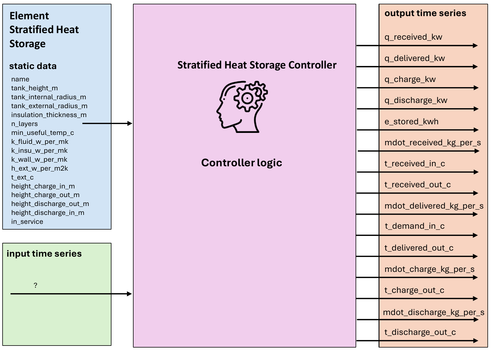
Input Static Data
Parameter |
Description |
Unit |
|---|---|---|
name |
A custom name for this Stratified Heat Storage |
N/A |
tank_height_m |
The height of the storage tank |
m |
tank_internal_radius_m |
The internal radius of the storage tank |
m |
tank_external_radius_m |
tank_external_radius (without insulation) |
m |
insulation_thickness_m |
insulation thickness |
m |
n_layers |
|
N/A |
min_useful_temp_c |
Temperature used as a threshold to calculate the amount of stored energy |
Degree Celsius |
k_fluid_w_per_mk |
Thermal conductivity of storage fluid (prosumer.fluid) |
Degree Celsius |
k_insu_w_per_mk |
Thermal conductivity of insulation |
W/(mK) |
k_wall_w_per_mk |
Thermal conductivity of the tank wall |
W/(mK) |
h_ext_w_per_m2k |
Heat transfer coefficient with the environment (Convection between tank and air) |
W/(m²K) |
t_ext_c |
The ambient temperature used for calculating heat losses |
Degree Celsius |
max_remaining_capacity_kwh |
The difference between the maximum energy that can be stored in the storage and\ the actual stored energy from which the storage will not require to be filled anymore |
kWh |
t_discharge_out_tol_c |
The maximum allowed difference between the demand temperature and the temperature of\ the top layer in the storage to allow supplying the demand |
Degree Celsius |
max_dt_s |
The temporal resolution of the storage calculation. Default to the period resolution.\ May cause divergence of the model if too high. |
second |
height_charge_in_m |
The height of the inlet charging point in m. |
m |
height_charge_our_m |
The height of the outlet charging point in m. |
m |
height_discharge_in_m |
The height of the inlet discharging point in m. |
m |
height_discharge_out_m |
The height of the outlet discharging point in m. |
m |
Input Time Series
Parameter |
Description |
Unit |
|---|---|---|
mdot_discharge_kg_per_s |
Mass flow rate of discharge |
kg/s |
t_discharge_c |
Discharge temperature |
°C |
q_delivered_kw |
Delivered heat power |
kW |
e_stored_kwh |
Stored energy |
kWh |
Output Time Series
Parameter |
Description |
Unit |
|---|---|---|
mdot_discharge_kg_per_s |
The storage discharge mass flow |
kg/s |
t_discharge_c |
The storage discharge temperature |
Degree Celsius |
q_delivered_kw |
The storage delivered power to the downstream elements |
kW |
e_stored_kwh |
The total stored heat energy in the storage above the element minimum usefully temperature compared to the initial state |
kWh |
Mapping
The Stratified Heat Storage Controller can be mapped using FluidMixMapping.
The stratified heat storage can be used as responder for a FluidMix mapping, taking the output from another controller as its input
The stratified heat storage can be used as initiator for a FluidMix mapping, making its output to another controller
Model
- class pandaprosumer.controller.models.stratified_heat_storage.StratifiedHeatStorageController(prosumer, stratified_heat_storage_object, order, level, init_layer_temps_c=None, plot=False, bypass=True, in_service=True, index=None, name=None, **kwargs)[source]
Controller for stratified heat storage systems.
The stratified heat storage is implemented from Untrau et al., A fast and accurate 1-dimensional model for dynamic simulation and optimization of a stratified thermal energy storage, 2023
Model a stratified thermal energy storage, which uses one single tank that is charged from the top with hot fluid while the cold fluid returning to the storage is charged from the bottom. The model assumes a vertical discretization of the tank with layers of uniform temperatures
When charging with the mapped feed temperature and mass flow, the return temperature is the one on the bottom layer of the storage. When discharging with the return temperature and mass flow required by the downstream elements, the discharge temperature is the one on top of the storage.
Note that the time step should not be too long compared to the volume of a layer and the (dis)charging mass flow so that less than the volume of a layer will be displaced in a time step.
- Parameters:
prosumer – The prosumer object
stratified_heat_storage_object – The stratified heat storage object
order – The order of the controller
level – The level of the controller
init_soc – Initial state of charge
in_service – The in-service status of the controller
index – The index of the controller
kwargs – Additional keyword arguments
Thermal energy storage means heating or cooling a medium to use the energy when needed later. In its simplest form, this could mean using a water tank for heat storage, where the water is heated at times when there is a lot of energy, and the energy is then stored in the water for use when energy is less plentiful. Thermal energy storage can also be used to balance energy consumption between day and night. Storage solutions include water or storage tanks of ice-slush, earth or bedrock accessed via boreholes and large bodies of water deep below ground. The Stratified thermal energy storage model developed is a sensible thermal energy storage that uses a water tank for storing and releasing heat energy. The stratification inside the storage tank between the hot and the cold water is illustrated in Figure 1 [USM+23].
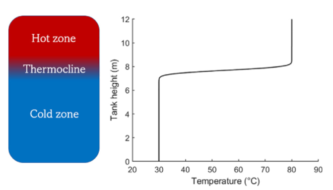
The thermocline region and the temperature profile inside the tank [USM+23]
Assuming constant thermo-physical properties for the storage fluid and no heat source inside the storage tank, the conservation of energy in 1D leads to the following Partial Differential Equation (P.D.E.) with the temperature T as unknown:
The first term is the energy accumulation, the second term represents the enthalpy fluxes due to the charge or discharge, the third term represents diffusion inside the tank and the final term models the heat losses to the environment. In this equation, the unknown variable is the storage fluid temperature T(z, t) varying in space, along the vertical coordinate z, and in time t; ρ represents the stored fluid density, Cp the stored fluid heat capacity and k the stored fluid thermal conductivity. They are all assumed uniform and constant. A is the tank cross-sectional area, P is its perimeter. U is the heat transfer coefficient with the environment.
Boundary conditions at the top and bottom of the storage tank:
When Charging:
When Discharging:
During idle time:
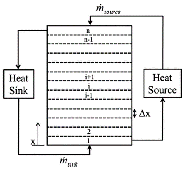
Finite volume discretization scheme for the stratified thermal energy storage model [USM+23]
The previous Partial Differential Equation is discretized explicitly with the Euler-forward scheme. The equations used to solve for the new temperature for the different layers i are presented hereafter:
To further improve the numerical stability and accuracy—especially in convection-dominated regimes during charging or discharging—the model implements a Total Variation Diminishing (TVD) scheme. This scheme is designed to:
Prevent Spurious Oscillations: By ensuring that the total variation of the temperature profile does not increase over time, the TVD approach avoids non-physical oscillations that can arise with standard upwind or central difference schemes.
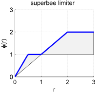
Preserve Sharp Temperature Gradients: The TVD method utilizes a flux limiter (the superbee limiter) to maintain steep temperature fronts while ensuring numerical stability.
For the first layer at the bottom of the storage tank:
For an intermediate layer i, for i varying from 2 to N:
We first define :
Where \(\dot{m}_{\text{c}}\) is the charging mass flow rate [kg/s] and \(\dot{m}_{\text{d}}\) is the discharging mass flow rate [kg/s],
The sign of \(\dot{m}_{b}\) determines the direction of flow:
For positive \(\dot{m}_{b}\) (charging):
An additional term incorporating the TVD scheme is included to prevent spurious oscillations:
Where \(\phi_i\) is the superbee limiter function. and \(\Delta T_i = T_{i+1} - T_i\)
For negative \(\dot{m}_{b}\) (discharging):
The total temperature update for each layer is then:
For the last layer N at the top of the storage tank:
The superbee limiter is a flux limiter used in Total Variation Diminishing (TVD)
schemes to control spurious oscillations near sharp gradients or discontinuities.
In our implementation, the function phi(r) computes the limiter value based on the ratio
\(r\) of successive gradients, defined as:
The superbee limiter is then given by:
This careful balance allows the TVD scheme to be both robust and accurate in capturing steep temperature fronts, making it particularly effective for convection-dominated problems such as those encountered in stratified heat storage models.