Heat Exchanger
See also
Note
A heat exchanger consists of an element and a controller. The element defines it’s physical parameters, while the controller governs the operational logic.
The create_controlled function creates both and connects them.
Create Controlled Function
- pandaprosumer.create_controlled_heat_exchanger(prosumer, t_1_in_nom_c=90, t_1_out_nom_c=65, t_2_in_nom_c=50, t_2_out_nom_c=60, mdot_2_nom_kg_per_s=0.4, delta_t_hot_default_c=5, max_q_kw=None, min_delta_t_1_c=5, primary_fluid=None, secondary_fluid=None, name=None, index=None, in_service=True, level=0, order=0, period=0, **kwargs)[source]
Creates a heat exchanger element in prosumer[“heat_exchanger”] and an heat exchanger controller
- INPUT:
prosumer - The prosumer within this heat exchanger should be created
- OPTIONAL:
t_1_in_nom_c (float, default 90) - Primary nominal input temperature [C]
t_1_out_nom_c (float, default 65) - Primary nominal output temperature [C]
t_2_in_nom_c (float, default 50) - Secondary nominal input temperature [C]
t_2_out_nom_c (float, default 60) - Secondary nominal output temperature [C]
mdot_2_nom_kg_per_s (float, default 0.4) - Secondary nominal mass flow [kg/s]
delta_t_hot_default_c (float, default 5) - Default difference between the hot (feed) temperatures [C]
max_q_kw (float, default None) - Maximum heat power through the heat exchanger [kW]
min_delta_t_1_c (float, default 5) - Minimum temperature difference at the primary side [C]
primary_fluid (string, default None)* - Fluid at the primary side of the heat exchanger. If None, the prosumer’s fluid will be used
secondary_fluid (string, default None) - Fluid at the secondary side of the heat exchanger. If None, the prosumer’s fluid will be used
name (string, default None) - The name for this heat exchanger
index (int, default None) - Force a specified ID if it is available. If None, the index one higher than the highest already existing index is selected.
in_service (boolean, default True) - True for in_service or False for out of service
level (int, default 0) - The level of the controller
order (int, default 0) - The order of the controller
period (int, default 0) - Index of the period, default is 0
- OUTPUT:
index (int) - The unique ID of the created heat exchanger
- EXAMPLE:
create_controlled_heat_exchanger(prosumer, “heat_exchanger1”)
Controller
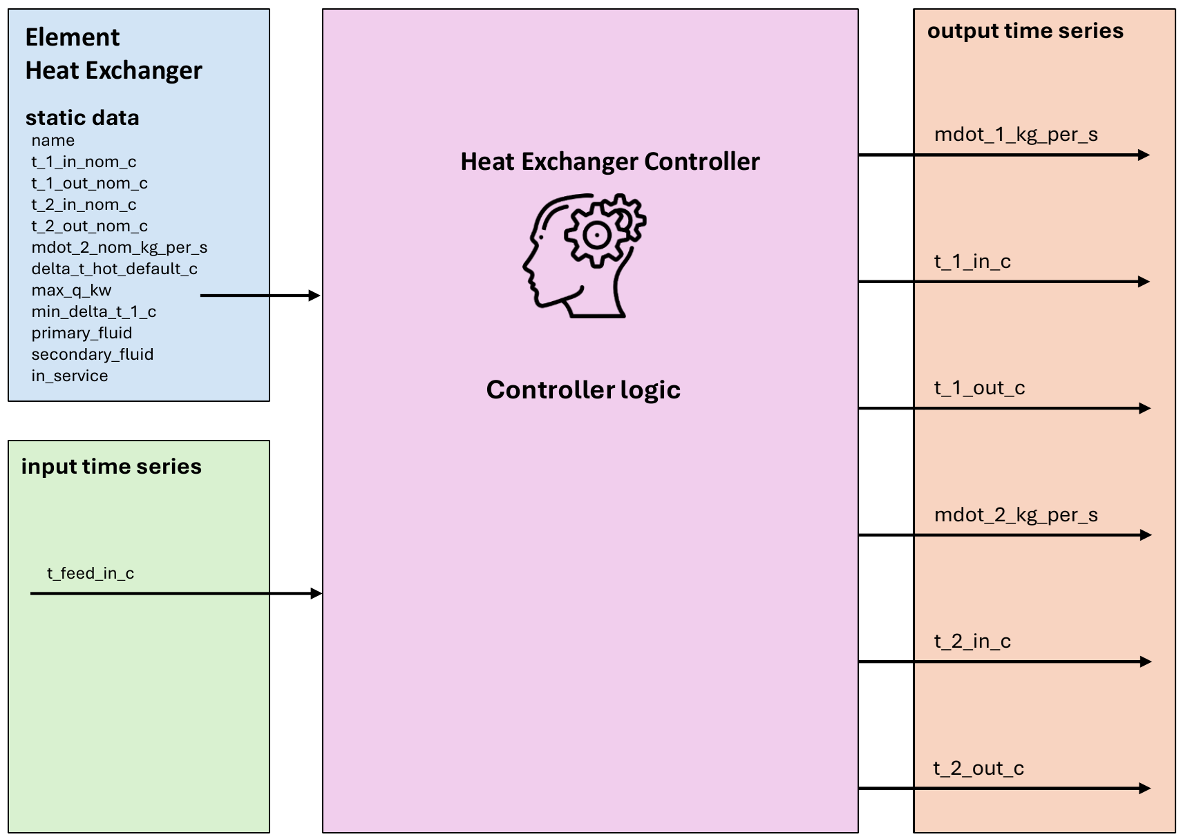
Input Static Data
These are the physical parameters required for the Heat Exchanger element to enable the model calculation:
Parameter |
Description |
Unit |
|---|---|---|
name |
Unique name or identifier for the Heat Exchanger element. |
N/A |
t_1_in_nom_c |
Primary nominal input temperature |
Degree Celsius |
t_1_out_nom_c |
Primary nominal output temperature |
Degree Celsius |
t_2_in_nom_c |
Secondary nominal input temperature |
Degree Celsius |
t_2_out_nom_c |
Secondary nominal output temperature |
Degree Celsius |
mdot_2_nom_kg_per_s |
Secondary nominal mass flow |
kg/s |
delta_t_hot_default_c |
Default difference between the hot (feed) temperatures |
Degree Celsius |
max_q_kw |
Maximum heat power through the heat exchanger |
kW |
min_delta_t_1_c |
Minimum temperature difference at the primary side |
Degree Celsius |
primary_fluid |
Fluid at the primary side of the heat exchanger. If None, the prosumer’s fluid will be used |
N/A |
secondary_fluid |
Fluid at the secondary side of the heat exchanger. If None, the prosumer’s fluid will be used |
N/A |
Input Time Series
t_feed_in_c |
The feed temperature from the heating network |
Degree Celsius |
Output Time Series
Parameter |
Description |
Unit |
|---|---|---|
mdot_1_kg_per_s |
The mass flow rate at the primary side of the heat exchanger |
kg/s |
t_1_in_c |
The feed input temperature at the primary side of the heat exchanger |
Degree Celsius |
t_1_out_c |
The return output temperature at the primary side of the heat exchanger |
Degree Celsius |
mdot_2_kg_per_s |
The mass flow rate at the secondary side of the heat exchanger |
kW |
t_2_in_c |
The return input temperature at the secondary side of the heat exchanger |
Degree Celsius |
t_2_out_c |
The feed output temperature at the secondary side of the heat exchanger |
Degree Celsius |
Mapping
The Heat Exchanger Controller can be mapped using FluidMixMapping.
The heat exchanger can be used as responder for a FluidMix mapping, taking the output from another controller as its input
The following outputs are mapped:
mdot_2_kg_per_st_2_out_c
Model
- class pandaprosumer.controller.models.HeatExchangerController(prosumer, stratified_heat_storage_object, order, level, in_service=True, index=None, name=None, **kwargs)[source]
Controller for Heat Exchanger systems.
The heat exchanger is implemented from KS conservation and logarithmic mean temperature difference (LMTD)
In the heat exchanger element some nominal temperatures and mass flows are specified. The resulting return temperature on the primary side is calculated from this state, then the primary mass flow is deducted.
The temperature on the primary side must be higher than on the secondary (t_in_1 > t_out_2 and t_out_1 > t_in_2).
Primary: t_in_1 = t_hot_1 = t_feed_1 t_out_1 = t_cold_1 = t_return_1 (result of _compute_temp)
Secondary: t_in_2 = t_cold_2 = t_return_2 t_out_2 = t_hot_2 = t_feed_2
- Parameters:
prosumer – The prosumer object
heat_exchanger_object – The heat exchanger object
order – The order of the controller
level – The level of the controller
in_service – The in-service status of the controller
index – The index of the controller
kwargs – Additional keyword arguments
- calculate_heat_exchanger(prosumer, t_2_out_c, t_2_in_c, mdot_2_kg_per_s, t_1_in_c)[source]
Main Heat Exchanger calculation method
- Parameters:
prosumer – The prosumer object
t_2_out_c – The secondary output (hot feed pipe) temperature
t_2_in_c – The secondary input (cold return pipe) temperature
mdot_2_kg_per_s – The secondary mass flow
t_1_in_c – The primary input (hot feed pipe) temperature
- calculate_heat_exchanger_reverse(prosumer, t_1_in_c, t_1_out_c, mdot_1_kg_per_s, t_2_in_c)[source]
Air Cooled Heat Exchanger calculation method based on LMTD method from nominal conditions
- Parameters:
prosumer – The prosumer object
t_1_in_c – The input temperature of the fluid in °C
t_1_out_c – The output temperature of the fluid in °C
mdot_1_kg_per_s – Mass flow rate of the fluid in kg/s
t_2_in_c – The input temperature of the air in °C
- Returns:
The output mass flow rate of the air in kg/s, the input and output temperature of the air in °C, the output mass flow rate of the fluid in kg/s, the input and output temperature of the fluid in °C
- control_step(prosumer)[source]
Executes the control step for the controller.
- Parameters:
prosumer – The prosumer object
- t_m_to_receive_for_t(prosumer, t_feed_c)[source]
For a given feed temperature in °C, calculate the required feed mass flow and the expected return temperature if this feed temperature is provided.
- Parameters:
prosumer – The prosumer object
t_feed_c – The feed temperature
- Returns:
A Tuple (Feed temperature, return temperature and mass flow)
Model of a simple heat exchanger based on logarithmic mean temperature difference (LMTD) calculation with countercurrent flows.
The primary side of the heat exchanger should be the hot side get heat from a District Heating Network.
The secondary side should be the cold connected to downstream elements in the prosumer.
The model is based on a nominal state for which all the temperatures and mass flows \(T_{1_{\text{in}_n}}\), \(T_{1_{\text{out}_n}}\), \(T_{2_{\text{in}_n}}\), \(T_{2_{\text{out}_n}}\) and \(\dot{m}_{2_n}\) are known.
Then given \(\dot{m}_2\), \(T_{2_\text{in}}\), \(T_{2_\text{out}}\) and \(T_{1_\text{in}}\) for another state, the model can calculate \(T_{1_\text{out}}\) and \(\dot{m}_1\).
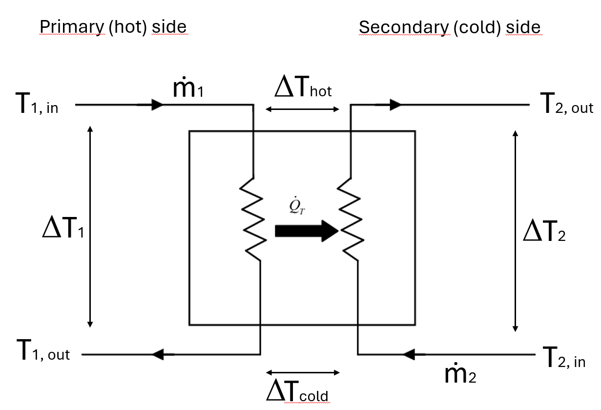
Schematic representation of a heat exchanger considered by EIFER during modeling
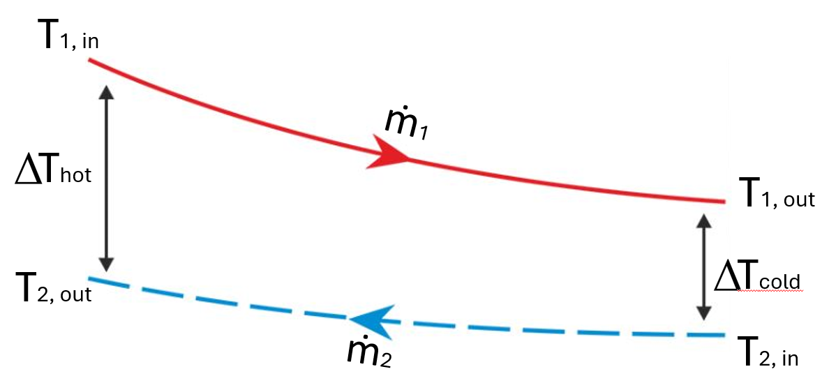
The LMTD illustrated in a countercurrent temperature profile
The logarithmic mean temperature difference (LMTD) is defined as
The LMTD can be used to find the exchanged heat in the heat exchanger:
So
From that we derive:
With
This equation is solved by dichotomy to find \(X\), then \(\Delta T_\text{cold}\), then \(T_{1_\text{out}}\).
Assuming no heat losses, we then derive \(\dot{m}_1\) given that
Note
\(a = 1\) means that \(X = 0\) so \(\Delta T_\text{cold} = \Delta T_\text{hot}\) (it corresponds to a limit case where the LMTD is not defined)
\(0 < a < 1\) means that \(X < 0\) so \(\Delta T_\text{cold} > \Delta T_\text{hot}\)
\(a > 1\) means that \(0 < X < 1\) so \(\Delta T_\text{cold} < \Delta T_\text{hot}\)
Note
\(X > 1\) would mean \(\Delta T_\text{cold} < 0\), so \(T_{1_\text{out}} < T_{2_\text{in}}\), which is not possible for the heat exchange
\(a << 1\) would mean \(\Delta T_\text{cold} >> \Delta T_\text{hot}\), so \(T_{1_\text{out}} > T_{1_\text{in}}\) which is not possible for a countercurrent flows
If the calculated \(T_{1_\text{out}}\) is geater than the input primary temperature \(T_{1_\text{in}}\), then \(T_{1_\text{out}}\) is set to \(T_{1_\text{in}}\) and the mass flow \(\dot{m}_1\) is set to 0.
If \(a = 0\), then the mass flow \(\dot{m}_1\) is set to a small value of 0.2 m3/h.
If the transferred power is greater than the maximum power of the heat exchanger \(Q_{\text{max}}\), the secondary mass flow \(\dot{m}_2\) is set to \(\frac{Q_{\text{max}}}{Cp_2 \Delta T_2}\) so the transferred power is equal to the maximum power before solving for \(T_{1_\text{out}}\).
A minimum value of the parameter \(a\), \(a_\text{min}\) is calculated from the maximum cold temperature that can be reached at the outlet of the primary side \(T_{1_{\text{out}_\text{max}}}\). \(a_\text{min} = -\frac{ln(1-x_\text{min})}{x_\text{min}}\) with \(x_\text{min} = 1 - \frac{\Delta T_{\text{cold}_\text{max}}}{\Delta T_\text{hot}}\). If \(a < a_\text{min}\), the secondary mass flow \(\dot{m}_2\) is set so that \(Q_r = Q_{r_n} * \frac{\Delta T_\text{hot}}{a_\text{min} * LMTD_n}\), and \(T_{1_{\text{out}}}\) is set to \(T_{1_{\text{out}_\text{max}}}\)
If \(a > a_\text{max}\), the temperature difference between the primary and secondary side \(\Delta T_\text{hot}\) may be too high or the transferred heat \(Q_r\) too small compared to the nominal conditions. In this case the dichotomy cannot be solve with sufficient precision and no heat exchange is assumed, setting \(T_{1_\text{out}} = T_{1_\text{in}}\) and \(\dot{m}_1 = 0\).
After this calculations, if \(\dot{m}_1 = 0\), the secondary mass flow \(\dot{m}_2\) is set to 0 and the secondary output temperature \(T_{2_\text{out}}\) is set to \(T_{2_\text{in}}\).
If the calculated primary mass flow \(\dot{m}_1\) is greater than the maximum mass flow available \(\dot{m}_{1_\text{max}}\), then the secondary mass flow \(\dot{m}_2\) is set so that \(Q_r = \dot{m}_{1_\text{max}} * Cp_1 * \Delta T_1\), considering the same \(\Delta T_1\) as first calculated.