Heat Pump
See also
Note
A heat pump consists of an element and a controller. The element defines its physical parameters, while the controller governs the operational logic.
The create_controlled function creates both and connects them.
Create Controlled Function
- pandaprosumer.create_controlled_heat_pump(prosumer, delta_t_evap_c=15.0, carnot_efficiency=0.5, pinch_c=None, delta_t_hot_default_c=5, max_p_comp_kw=nan, min_p_comp_kw=nan, max_ramp_up_kw_per_s=nan, max_ramp_down_kw_per_s=nan, max_t_cond_out_c=nan, max_cop=nan, cond_fluid=None, evap_fluid=None, mode='carnot', name=None, index=None, in_service=True, level=0, order=0, period=0, **kwargs)[source]
Creates a heat pump element in prosumer[“heat_pump”] and an heat pump controller
- INPUT:
prosumer - The prosumer within this heat pump should be created
- OPTIONAL:
delta_t_evap_c (float, default 15) - Constant temperature difference at the evaporator [C]
carnot_efficiency (float, default 0.5) -
pinch_c (float, default 15) -
delta_t_hot_default_c (float, default 5) - Default difference between the hot (feed) temperatures [C]
name (string, default None) - A custom name for this heat pump
index (int, default None) - Force a specified ID if it is available. If None, the index one higher than the highest already existing index is selected.
in_service (boolean, default True) - True for in_service or False for out of service
max_p_comp_kw (float, default None) - Power of the compressor [kW]
min_p_comp_kw (float, default None) - Minimum working power of the compressor [kW]
max_ramp_up_kw_per_s (float, default None) - Maximum ramping up speed of the compressor [kW/s]
max_ramp_down_kw_per_s (float, default None) - Maximum ramping down speed of the compressor [kW/s]
max_cop (float, default None) - Maximum COP
cond_fluid (str, default None) - Fluid at the condenser. If None, the prosumer’s fluid will be used
evap_fluid (str, default None) - Fluid at the evaporator. If None, the prosumer’s fluid will be used
mode (str, default ‘carnot’) - COP calculation mode. Options: ‘carnot’ or ‘lorenz’ (case insensitive)
level (int, default 0) - The level of the controller
order (int, default 0) - The order of the controller
period (int, default 0) - Index of the period, default is 0
- OUTPUT:
index (int) - The unique ID of the created heat pump controller
- EXAMPLE:
create_controlled_heat_pump(prosumer, “heat_pump1”)
Controller
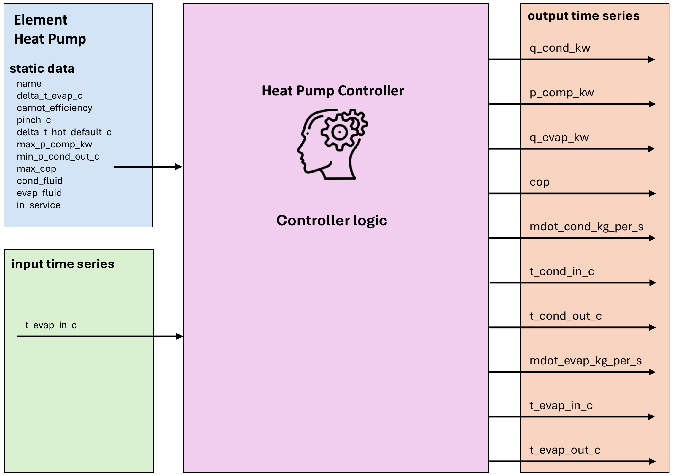
Input Static Data
Parameter |
Description |
Unit |
||
|---|---|---|---|---|
name |
A custom name for this heat pump |
N/A |
||
delta_t_evap_c |
Constant temperature difference at the evaporator |
Degree Celsius |
||
carnot_efficiency |
Carnot efficiency, usually between 0.4-0.6, used to simplify the calculation of the heat pump COP |
N/A |
||
pinch_c |
Minimum temperature difference between the heat pump and the heat source/sink (pinch temperature) |
Degree Celsius |
||
delta_t_hot_default_c |
Default temperature difference between condenser outlet and inlet on the hot side |
Degree Celsius |
||
max_p_comp_kw |
Maximum power of the compressor |
kW |
||
min_p_comp_kw |
Minimum working power of the compressor |
kW |
||
max_ramp_up_kw_per_s |
Maximum ramp-up rate of electrical power |
kW/s |
||
max_ramp_down_kw_per_s |
Maximum ramp-down rate of electrical power |
kW/s |
||
max_t_cond_out_c |
Maximum condenser outlet temperature |
Degree Celsius |
||
max_cop |
Maximum COP |
N/A |
||
cond_fluid |
Fluid at the condenser. If None, the prosumer’s fluid will be used |
N/A |
||
evap_fluid |
Fluid at the evaporator. If None, the prosumer’s fluid will be used |
N/A |
||
mode |
COP calculation mode. Options: ‘carnot’ (default) or ‘lorenz’ |
str |
‘carnot’ or ‘lorenz’ |
No |
overflow_strategy |
How to dispatch surplus mass flow to responders when the heat pump is clamped to |
str |
||
in_service |
True for in_service or False for out of service |
boolean |
Input Time Series
Parameter |
Description |
Unit |
|---|---|---|
t_evap_in_c |
Temperature of the heat source at the inlet of the evaporator. |
Degree Celsius |
Output Time Series
Parameter |
Description |
Unit |
|---|---|---|
q_cond_kw |
The provided power at the heat pump condenser |
kW |
p_comp_kw |
The compressor consumed electrical power |
kW |
q_evap_kw |
The extracted power at the heat pump evaporator |
kW |
cop |
The operating Coefficient Of Performance |
N/A |
mdot_cond_kg_per_s |
The mass flow rate at the condenser of the heat pump |
kg/s |
t_cond_in_c |
The input temperature at the condenser of the heat pump (return pipe) |
°C |
t_cond_out_c |
The output temperature at the condenser of the heat pump (feed pipe) |
°C |
mdot_evap_kg_per_s |
The mass flow rate at the evaporator of the heat pump |
kg/s |
t_evap_in_c |
The input temperature at the evaporator of the heat pump (feed pipe) |
°C |
t_evap_out_c |
The output temperature at the evaporator of the heat pump (return pipe) |
°C |
Mapping
The Heat Pump Controller can be mapped using FluidMixMapping.
The heat pump can be used as responder for a FluidMix mapping, taking the output from another controller as its input
The following outputs are mapped:
mdot_kg_per_st_cond_out_c
Note
If the heat pump is not mapped as a responder, it is considered to be connected to free air. In this case, the input t_evap_in_c should be mapped from a timeseries of the ambient air temperature.
Model
- class pandaprosumer.controller.models.heat_pump.HeatPumpController(prosumer, heat_pump_object, order, level, in_service=True, index=None, name=None, **kwargs)[source]
Controller for heat pumps.
- Parameters:
prosumer – The prosumer object
heat_pump_object – The heat pump object
order – The order of the controller
level – The level of the controller
in_service – The in-service status of the controller
index – The index of the controller
kwargs – Additional keyword arguments
- control_step(prosumer)[source]
Executes the control step for the controller.
- Parameters:
prosumer – The prosumer object
- t_m_to_receive_for_t(prosumer, t_feed_c)[source]
For a given feed temperature in °C, calculate the required feed mass flow and the expected return temperature if this feed temperature is provided.
- Parameters:
prosumer – The prosumer object
t_feed_c – The feed temperature
- Returns:
A Tuple (Feed temperature, return temperature and mass flow)
The evaporator of the heat pump should get heat from a District Heating Network or from the ambient air.
The condenser should be connected to downstream elements in the prosumer or to a District Heating Network.
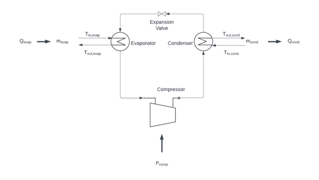
Schematic representation of a thermal-based heat pump considered by EIFER during modeling (source: own creation)
To understand the thermal-based heat pump model developed by EIFER, it is first necessary to have an overview of the technologies and parameters involved in the modelling of a heat pump. Figure 4 offers a schematic representation of a thermal-based heat pump considered by EIFER during modelling.
The thermal-based heat pump modelled includes a compressor, a condenser, an expansion valve, and an evaporator. In general terms, a heat pump requires a certain amount of power \(P_\text{comp}\), it transfers a certain amount of heat \(Q_\text{cond}\) to the heat sink, and it absorbs a certain amount of heat \(Q_\text{evap}\) from the heat source.
The thermal-based heat pump model developed by EIFER calculates the required heat pump mass flow on the evaporator (\(\dot{m}_\text{evap}\)) to produce enough heat (Qcond) to meet the requirements of the network in terms of temperature increase (\(T_{\text{out}_\text{cond}} - T_{\text{in}_\text{cond}}\)) with a given mass flow (\(\dot{m}_\text{cond}\)).
To do so, a series of parameters are required as a given input from the model developed:
\(T_{\text{out}_\text{cond}}\): target temperature need from the network.
\(T_{\text{in}_\text{cond}}\): return temperature from the network to the considered HP.
\(\dot{m}_\text{cond}\): mass flow in the network, which for simplicity is considered water.
\(T_{\text{in}_\text{evap}}\): temperature of the heat source at the inlet of the evaporator.
\(\Delta T_\text{evap}\): it is the temperature difference between the inlet and outlet of the evaporator on the heat source side.
\(Pinch\): it is a small temperature difference, usually in between 5-10 K, to account for temperature difference between the heat pump side and the heat source (or heat sink) side.
\(\eta_\text{C}\): Carnot efficiency, usually between 0.4-0.6, used to simplify the calculation of the heat pump COP
\(T_{\text{out}_{\text{cond}_\text{max}}}\): it is the maximum temperature that can be achieved at the outlet of the condenser on the heat sink side, it is usually given from the HP manufacturer and it depends on the refrigerant chosen.
Then, the calculation steps modelled follow the equations presented below:
The first step is to calculate the condenser thermal demand \(Q_\text{cond}\), meaning the thermal need from the network
Where \(Cp_\text{cond}\) is the specific heat capacity at constant pressure of the fluid used in the heat network, which is usually water
Then the temperature at the outlet of the evaporator is calculated (\(T_{\text{out}_\text{evap}}\))
Thanks to step n°2 it is possible to calculate the Carnot COP (\(COP_\text{C}\))
Which allows a simplified calculation of the heat pump COP (\(COP_\text{HP}\))
The required electrical power \(P_\text{comp}\) to provide \(Q_\text{cond}\) is also calculated
From which it is possible to derive the heat required from the heat source \(Q_\text{evap}\)
And finally the mass flow \(\dot{m}_\text{evap}\) needed at the evaporator for the HP to provide the required \(Q_\text{cond}\) Where \(Cp_\text{evap}\) is the specific heat capacity at constant pressure of the fluid used in the heat sink
It is important to check that the temperature at the outlet of the condenser is not above the maximum temperature achievable from the considered HP with the given refrigerant, otherwise that means that the maximum heat that can be provided to the network is lower than the requirement
If the COP is higher than the maximum COP of the HP, the power consumption is set to the maximum power, \(T_{\text{out}_\text{cond}}\) is also recalculated based on the maximum COP.
If the power consumption is higher than the maximum power of the HP, \(\dot{m}_\text{cond}\) is recalculated so that the power consumption is set to the maximum power.
If the power consumption is lower than the minimum power of the HP, the heat pump is considered off and the power consumption is set to zero,
Note
Limitations of the model:
Assume a constant \(\Delta T_\text{evap}\)
Assume a constant \(\eta_\text{C}\)
The model does not account for dynamic effects such as thermal inertia or transient behavior.
The model assumes ideal behavior and does not include efficiency losses due to real-world factors like friction or heat loss.
Edge Cases and Error Handling
The heat pump model includes several edge case handling mechanisms:
Ramp Up/Down Constraints: The model has the option to enforce maximum ramp-up and ramp-down rates for the compressor power to simulate realistic operational constraints.
Temperature Limits: The model checks and enforces maximum condenser outlet temperature limits to stay in realistic ranges.
COP Limits: The model enforces maximum COP limits to ensure realistic performance characteristics.
Power Limits: The model enforces both minimum and maximum power limits for the compressor. The option to add a minimum power ensures a simulation operating closer to real systems contraints.
Mass Flow Constraints: The model handles cases where the evaporator mass flow differs from the required mass flow by implementing bypass logic (to handle any extra mass flow at the evaporator) or recalculating the heat demand (if the available mass flow at the evaporator is not enough for the heat pump to satisfy the demand).
Shutdown Conditions: The model properly handles shutdown conditions when there is no demand on the condenser or when operational limits are exceeded.